Why is Audio Note's 1x oversampling unique?
Support Information from Andy Grove
Nowadays digital processing technology is so cheap that even in a commercial product the oversampling frequency need not be an integer multiple of the original rate. Techniques such as polyphase filtering mean that the incoming and outgoing sampling frequencies of the digital filter block can be totally unrelated. This brings sample rate converters into the picture. Generally when the higher frequency sampling rate is a direct multiple of the original incoming sample rate it is referred to as oversampling, when it is not a direct multiple and is derived from a different clock it is referred to as upsampling. Upsampling is attractive to engineers because it promises to eliminate jitter. (remember that with upsampling the input and output clock frequencies are derived from different sources).
It is not all sunshine and roses for the digital filtering guys because the filter algorithms used tend to completely screw up the transient response of the system. An FIR digital brickwall (using sinc function, this is the type most commonly used) has a symmetrical in time transient response which means a signal has ringing before it arrives, a kind of pre-echo. Totally unnatural. FIR algorithms are poor, discrete in time analogues of analogue filters and are actually worse in performance than the analogue prototype. Another BIG problem, especially with complex algorithms like polyphase filtering is that during the calculation numbers will be generated which are way larger than the available bit length of the DSP block. Therefore there will be truncation errors aplenty.
Therefore, using logic:
When a set of samples is passed through a digital filter, what you get out won’t be an interpolated superset of the input samples, which is the fundamental premise of the whole technology, they will be an entirely new set of samples.
Therefore philosophically there is something wrong with digital filtering and this is proven in practical listening tests. Hence we do not oversample the input signal or digitally tamper with it at all. Hence 1x oversampling (not oversampled). And this also precludes the use of bitstream and delta sigma DACs, which rely on processing. Therefore we only use resistor ladder type DACs.
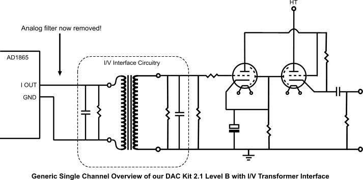
The output of most resistor ladder DAC chips is in the form of a current rather than a voltage. There are many ways to convert the current into a voltage but the most commonly used system is that of an op-amp connected as an I to V converter. This system requires the use of a high degree of feedback, and as a result there are problems associated with it. One of those is internal slew rate limiting of the op-amp itself. The rate of change of current at the output of even an audio DAC is very fast indeed. Even modern fast op-amps will slew limit internally and that affects sound quality. Some engineers have found that using extremely fast op-amps improves the sound quality, but we have completely sidestepped the issue by using a transformer I/V system. The transformer not only provides an I to V function but the way it is used in our latest DACs transfers maximum energy from the DAC chip itself. This in itself reduces overshoot and ringing and because the system is slightly overdamped the rise time is reduced to an acceptable rate as well.
Even a carefully chosen resistor used as an I/V converter can be successful if executed properly but the transformer system is sonically superior for the reasons of energy transfer outlined above.
The output from the I/V is fed into an amplifying stage, of course using valves. This can be a simple single valve stage up to a specialized line driver as found in the M3 to M8 preamps.